FAQ 常見問答
- Microcontrollers /
- MCU功能應用 /
- SN8PCxx Series /
- System Operation Mode
-
.In power down mode, how to set input pin to get the lowest current?
1. In sleep mode, the input pin should be set to input pull-up state and can not be set to floating state.
2. Two methods can be recommended to realize, which is as follows:
(1).Most Sonix chips have built-in programmable pull-up resistor for I/O port, customers can enable internal pull-up resistor in program.
For example: enable P1 pull-up resistormov A, #0FFh mov P1UR, A ; Enable Pull-up resistor by write 1 to P1UR .
(2). For input IO port without pull-up function (for example: sharing with RST input pin), it is proposed to add an external resistor (20Kohm) pulled to VDD.
In addition, users sometimes ask how to set IO port to save power. In fact, the input or output is the same, as long as the IO port to maintain a fixed state, not suspended, you can reduce the leakage current; of course, this way need external circuit output to determine the state. -
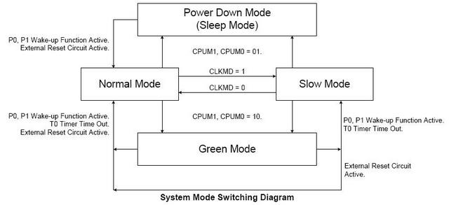
.The chip goes into sleep mode from low-speed mode and be waked up, what mode will the system work in?
SONIX MCU system mode switching diagram is as follows.
From the diagram you can see, whether the system is from low-speed mode or from normal mode to enter sleep mode, when the system is awakened, it will enter normal mode.
In addition, the system is awakened from the Green Mode, it will return to the original mode (normal mode or slow mode). -
.How to set in program to increase MCU stability in/out GREEN MODE?
In order to increase the stability of MCU in/out GREEN MODE, in mode switching, user should use a macro(this macro is included in IDE, in M2IDE_V115 and later versions, the path is C: \ Sonix \ M2IDE_V115 \ use_inc2, the corresponding series' inc is in the file), other switching modes must be done using the corresponding macros too.
For macro name of other operation modes, please refer to the following table:macro name macro length Note @SleepMode 1-word System enter Sleep Mode (Power Down). @GreenMode 3-word System enter Green Mode, including synchronization process. @SlowMode 2-word System enter Slow Mode, and stop high-speed oscillator. @NormalMode 5-word System Switch to Normal Mode from Slow Mode, the program includes starting high-speed oscillator, high-speed oscillator warm-up and system control program to switch to Normal Mode. -
.Why chips can not enter sleep mode?
The program can enter Sleep Mode by setting: B0BSET CPUM0, If the system can not enter Sleep Mode, please check the following three conditions:
1.Check watchdog settings, when you select Always on option, the system will not enter sleep mode;
2.Check whether Port0 input level signal changes, user need to decide whether pull-up Port0 depending on the actual situation;
3.Check whether Port1 be set enable wake-up function in program, if enable this function, the user needs to check whether Port1 input level signal changes.
These three conditions can make chips out of Sleep Mode, so users need to ensure the accuracy of external signals, and all ports with wake-up function should be pulled up. -
.How to set to enter low-speed mode properly?
Switching into low-speed mode can be divided into two situations: keep on external high-speed oscillator or external high-speed oscillator stopped.
1 If user cares little about power consumption, he can not stop the external high-speed oscillator.
Program settings are as follows:
B0BSET FCLKMD
2 Stop external high-speed oscillator to reduce power consumption.
B0BSET FCLKMD
B0BSET FSTPHX
The above instruction execution order can not be reversed, if user stops external high speed oscillator before switching into low speed mode, because the program is still running in the normal mode state at this time, once the oscillator stops vibration, the system will no longer execute, this will result in an error. For more information please refer to system operation mode section and system clock sections in datasheet. -
.How to set before entering power down mode for low power consumption?
Before entering Power down mode, you need to make some settings as follows:
1. First of all, set IO port according to I/O state, if the outside is low, the output is set to low, and if the input is high, set pull-up or output high. That is, to ensure IO has a fixed state.
2. Turn off LCD display (LCDBNK = 1), disable LCD driver (LCDENB = 0).
3. If you enable LBTENB function, as LBT has two different application circuit, the settings are different:
a) If use P4.1 and P4.2, P4.1 is set as IO port, close LBT function (LBTENB = 0);
b) If you only use P4.2 port, you only need to close the LBT function (LBTENB = 0) (note that there will be current leakage this connection method itself);
4. Disable CPR (AVEENB=0, ACMENB=0, AVDDRENB=0, BGRENB=0, CPRENB=0);
5. Disable ADC (ADCENB=0);
6. Disable PGIA (AMPENB=0); -
.What is the general power consumption for MCU in sleep mode?
MCU power consumption is minimum when enter Sleep Mode (not exceed 2uA). IC of engineering type, take SN8P2501B for example, in the temperature of -40 ℃ ~ 85 ℃, its Sleep Mode power consumption ranges from 10 to 21uA. There may be some slightly difference between different MCU types, you can refer to electrical characteristics section in datasheet for more information.
- Microcontrollers /
- MCU功能應用 /
- SN8PCxx Series /
- System Operation Mode